Chip Cube Dashboard Panel
Module Panel
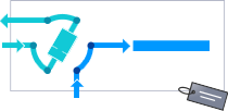
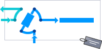
The items in the Chip Cube graphic have the following meaning and function:
|
| Indicates that an External Contacts board is installed. |
| The tooltip gives details (module type and serial number) of the linked pumps. |
| The form of the diagram is dependent on the inserted chip; it shows the current valve positions and flow path, for example, trapping mode (upper diagram) or analysis mode (lower diagram). The tooltip for the tag icon shows the information currently stored on the chip tag. |
Actuals
The following chip cube actuals are displayed:
Chip Load State | The current load state of the chip, for example, Standby or Operate. |
Inner Valve Position | The current position of the inner valve, for example, Enrichment or Analysis. |
Outer Valve Position | The current position of the outer valve. |
Chip Type | The part number of the installed chip. |
Operate time | The total time that the chip has been in the operating position. |
Current position time | The elapsed time since the chip was set to its current position. |
Trapping in progress | Whether trapping is currently in progress (True) or not (False). |
Trapping Volume | The current trapping volume (increased from 0 during the trapping phase). If no trapping is in progress, the volume is 0. |
Context Menu
The context menu contains the following commands:
| Displays the Chip Cube's Method Setup dialog box. |
|
|
| Causes the LED on the front of the module to blink for a few seconds. |
| Moves the chip out of the operating position to allow it to be unloaded. |
| Sets the pumps and MSD to standby mode, and moves the chip out of the spray chamber. |
| Moves the chip into the operating position. |
 Method