MWD Dashboard Panel
Module Graphic
The items in the MWD graphic have the following meaning and function:
|
|
Indicates that an External Contacts board is installed. |
|
|
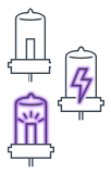
The color indicates the status of the Vis lamp:
|
|
|
The color indicates the status of the UV lamp:
|
|
|
Denotes a UV lamp with a lamp tag. The tooltip shows the information on the lamp tag. Color coding is as above. |
|
|
Denotes a detector cell with a cell tag. The tooltip shows the information on the cell tag. This graphic is present only when the detector cell includes a cell tag. |
| When balancing is in progress, the graphic is yellow (not ready). |


Actuals
The MWD actuals shows a table of the current signals in three columns:
|
Channel |
The signal definition:
|
WL | The signal wavelength (in nm). |
BW |
The bandwidth of the signal wavelength (in nm). |
|
RefWL |
The reference wavelength (in nm) or off. |
RefBW |
The bandwidth of the reference wavelength (in nm) or off. |
mAU |
The signal output (in mAU). |
Context Menu
The context menu contains the following commands:
|
|
Displays the detector's Control dialog box. |
|
|
Displays the detector's Method Setup dialog box. |
|
|
|
|
Causes the LED on the front of the device to blink for a few seconds. |
| Balances the detector. |
| Ignites the UV lamp. |
|
|
Switches off the UV lamp. |
|
|
Switches on the Vis lamp. This item is present only when the detector includes a Vis lamp. |
|
|
Switches off the Vis lamp. This item is present only when the detector includes a Vis lamp. |
 Control
 Method
 Balance
 Switch
on
Switch
on Switch
off
Switch
off
 Switch on
 Switch off