Evaluate the Delay Calibration
You can execute the Delay Calibration evaluation after a calibration run is completed, or later by clicking Evaluate Delay Calibration in Delay Calibration tab and opening an existing calibration run (ie run acquired via the Delay calibration tool).
A wizard opens with two different tabs.
Signal and Peaks tab
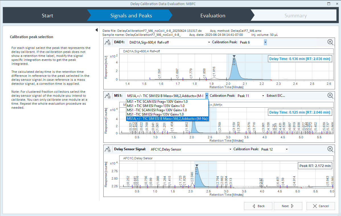
The Signals and Peaks tab displays the signals for all detectors configured in the instrument, one panel per detector, and an additional panel for the Fraction Collector Delay Sensor.
You can select in each detector panel the signal to be used, then the peak of interest. The system automatically computes the delay time and displays the value on detector signals.
You can modify the integration if required by clicking the Integration parameters button:

In case of MS detector, you can either select a MS trace (TIC SIM and SCAN) to compute the delay time or extract an ion chromatogram by clicking Extract EIC .., then use it to compute the delay time.
Evaluation tab
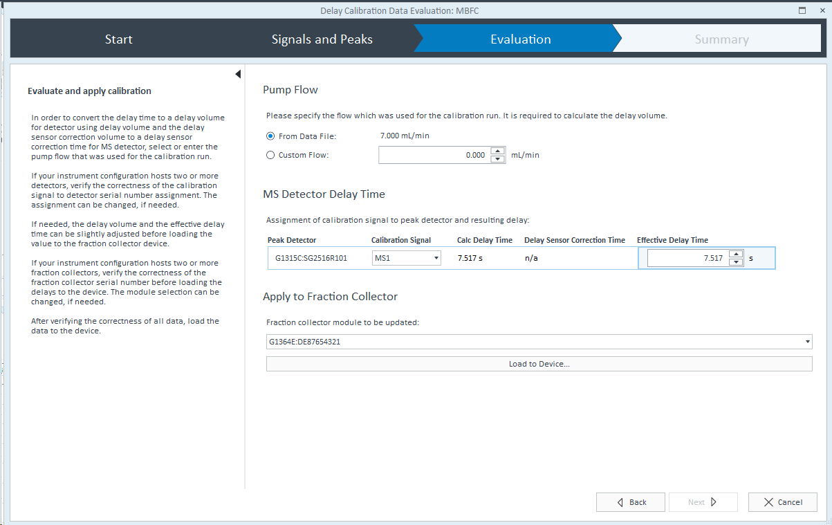
The Evaluation tab displays computed Delays and allows you to modify them if required.
Pump flow: The system uses the pump flow to compute the Delay Volume (for non-MS detector) and the Delay Sensor Correction Time (for MS detector). Flow is recovered from data file (from calibration run) or you can enter manually a flow (when using a non-Agilent pump for example). If the flow value changes, the system recalculates the delay volume and the Delay Sensor Correction Time automatically.
Detector Delay Volume(s): The system computes the Delay volume for non-MS detectors, it corresponds to the tubing volume between the detector and the fraction collector. Detector is identified by its part number and serial number, and the system automatically assigns a calibration signal. In case multiple detectors are present, you can select the expected signal for each detector.
Delay volume = (RT in FDS - RT in DET) x Pump flow
MS Detector Delay Time: The system computes the effective delay time for MS detector. It corresponds to the time taken by a compound to travel from MS detector to the fraction collector. The system calculates it based on the retention times of the peak selected in the chromatograms:
Effective delay time=(RT in FDS - RT in MSD) + Delay sensor correction time.
RT in FDS is the retention time of the peak selected for calibration in Fraction Collector Delay Sensor chromatogram.
RT in MSD is the retention time of the peak selected for calibration in Mass detector chromatogram.
Delay sensor correction time, corresponds Delay sensor correction volume x Flow. The Fraction Collector firmware reads the delay sensor correction volume. It corresponds to a slight correction of some µL (resulting in a time) that need to be applied due to the instrument configuration.
You can edit the computed delays if required.
Apply to Fraction Collector: You can load the calculated delays to the fraction collector module: delay volume for non-MS detectors (in mL) and delay time for MS detector (in seconds).
Once the data has loaded to the fraction collector, a delay calibration report is generated.
Click As calibrated (Time) in the acquisition method > fraction collector > Advanced to apply the calculated delays when running acquisitions.
base-id: 12878009867
id: 18014411387491851