About transfer volumes in instrument configuration
In the instrument configuration, you provide a transfer volume:
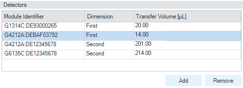
By default, this detectors table lists only CAN-based detectors. If you have connected an MSD or ELSD detector, you must add those detectors and their transfer volumes manually into the detectors table.
참고
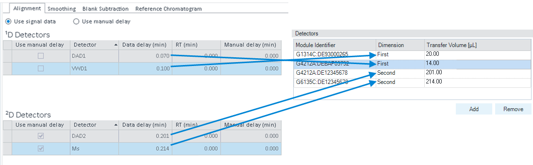
Ensure that you use the exact module identifier (detector name and serial number, separated by colon). Otherwise, the detector module cannot be identified, and the Data Delay (min) will be displayed as N/A in the processing method. In this case you have to align signals manually in the processing method (see Align signals manually).
The same detectors are, among others, also listed in the processing method under General > Signals > Alignment .
Transfer volume and transfer time
In the processing method, the Data Delay (min) corresponds to the detector transfer volume from the instrument configuration, divided by the respective pump flow. Therefore, the delay time can be seen as a transfer time.
In the processing method, all detectors are listed that are used in the data linked to the this method. If the method is not linked, and you have loaded different data from different instrument configurations with different transfer volumes, then the table in processing method displays various under Data Delay (min).
Difference to regular (1D) Data Analysis
In regular (1D) Data Analysis, only the delay (retention time difference) between two detectors has to be specified in the signal alignment. For the first ¹D detector, this value is always zero. In 2D-LC, the transfer time in the first dimension is measured from the detector to the 2D-LC valve.
See Also
Align signals over two dimensions
Learn more about signal alignment in the core Data Analysis.
base-id: 10237480203
id: 10237480203